How Do YOU Fix a Broken Motherboard Header Pin? (USB, CPU, 1394, case fan, IDE, etc)
The broken motherboard header pin issue is a classic issue with DIY-ers and MOD-ers… but there are a few things you can try to do to fix it. Some of them are really simple, but some of them are not. Please use this post as a source for ideas and possibilities and not a definitive guide to walk you through a guaranteed fix. This is NOT an exact science, so please use common sense and know your own limitations.
DISCLAIMER: I AM NOT RESPONSIBLE FOR ANY LOSS OR DAMAGE TO YOUR COMPUTER, DEVICES OR PERSON. USB PORTS THAT ARE NOT PROPERLY CONFIGURED CAN DAMAGE YOUR EQUIPMENT.

There. Now, where was I?…
I once noticed that one of my USB 3.0 ports was not working and I checked the connector only to realize the VBUS pin that is next to the missing / not connected (NC) pin was broken clean off at the base, with only a tiny spec of metal showing at the very bottom of the motherboard header output. While I was searching for a “do it yourself fix” or mod of some kind, I stumbled across this post and I’m sure I’m not the first to find it while trying to figure out what other people have done to fix this problem.
That is where I found this gem of a YouTube video that depicts what it is like when trying to fix a broken CPU pin:
I thought that the “Benny Hill fast-forward” was particularly hilarious, but only second to the reaction of success. ;oÞ
After doing the Google Dance and scanning through various sources, I discovered this is a common problem with the “solo VBUS pin” of the USB 3.0 header pin and socket . I kept searching and found a few great suggestions and the above YouTube Video relating to the bent / broken pin issue on good ole TomsHardware.com – An AWESOME resource for any MOD or DIY Computer project. That said, this is an issue that will keep arising until everything is like a USB, HMDI or similar one piece connection. That is not likely to happen anytime soon, but maybe someday…
I’ve done this same broken CPU pin trick for the above video before. If I remember right, it was a P.O.S. Cyrix CPU I bought from “The Old TigerDirect.com” back around 2000-2001. TigerDirect.com has come a VERY long way since then, and I LOVE that they bought out CompUSA and have select locations around the country. I am lucky enough to have two locations within a 30 minute drive, and sometimes buying things on the spot when you (or a client) are in a pinch. I remember being intrigued to see what the Cyrix CPU was going to be like, yet what I found in the package was 30% of the CPU pins rolling around in the flimsy little box that it came in when I opened the package. I was actually able to get this system to boot on the first try! For whatever reason, the pins seemed to have not set into the die of the cpu, but there were deep enough pits from the failed pin setting that it fit like a glove before and after I locked the CPU down into the socket.
I have also managed to “fashion” a pin from the right sized wire if the broken header pin is unusable, vanishes completely (where do they go??) or gets stuck in the connector to the point of no possible recovery (often rendering the connector useless with the header stuck in one of the holes). It is VERY tricky to get the of the wire piece length right, and if you use too flimsy of wire, its just going to flex and/or break off also. I know it is tedious, but measuring is a VERY good idea. Sometimes you are better off starting over with a new wire piece before getting it stuck into the connector and ruining it. I would use something AT LEAST as rigid as solid copper wire.
I have a few other ideas I’ve tried and worked, or some other proof of concept type things too.
As I was scouring the web, I was hoping to find a “solder-less solution”; I was searching for something like a standoff to fit the original socket exactly, but with a brand shiny new pins to overlap the motherboard header pins, and an extra pin (or a few pins) to slip into the bottom of the standoff to replace the broken ones.
Something like this… but in a ready-to-go USB 3.0 broken header pin repair kit:
I’ve seen this sort of “repair kit” type thing before with USB 1.0 and 2.0 headers, and other header types too, but not for a awhile now. I guess with everything getting so cheap, people just buy new… or… Try to RMA the products, hoping no one will ever notice. You know who you are…
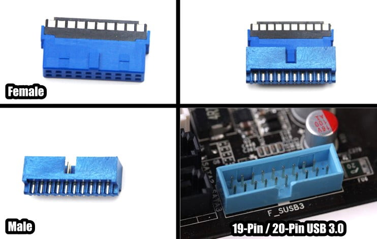
The newer USB 3.0 molex connectors are much larger and heavier than the old school multi-colored wires that connected to single pins. Does anyone else remember having to connect each wire to the USB 1/2 headers? Oi.
(INSERT IMAGE OF USB 3.0 Molex female connector – coming soon)
The downside to the old ways is that it was a PAIN IN THE @!$!$! to get all the individual pins correctly mounted to make the USB device function properly. It’s been almost a decade now since the “all lined up and ready to plug-in” usb header pin connectors have become the norm, but that beefy new USB 3.0 SuperSpeed (SS) connector that fits into the 19-pin (and apparently sometimes 20-pin) socket sticks up off the motherboard a lot farther, and it’s easy to bump it or push it up or down while working inside the case with everything all connected already.
(INSERT OLD STYLE USB HEADER IMAGE HERE – coming soon)
I believe I broke my VBUS pin while upgrading some case fans and tweaking my CPU water cooler configuration. I found one of my front panel USB 3.0 SuperSpeed (SS) ports was no longer working at all, not even powering a battery charger… I knew right away that something was up with the voltage pin for that port, and since the other USB 3.0 in the front panel was working fine, I did some investigating. Sure enough, I found my front panel USB 3.0 molex connector in the socket, though at an angle with only about 80% in the header pin socket at the top most part.
Doh!
I am not sure if I am lucky that I do not have to fuss with removing the rest of the pin from the socket, or I am cursed because I have very little contact area to make a connection to the motherboard.
Since this pin is next to the space where there is no pin connector in the 19-pin configuration, I could have tried to bend down the remaining stub and fit a small piece of wire into the connector and hook the tip of the wire under the bent pin. But I have an idea that just might be perfect for my situation…
If I can find a the right size diameter of a sewing straight pin with a flat head on the “not sharp” end, and trim off the excess length to fit into the connector and make contact with the broken off male USB 3.0 VBUS header pin, I will have a few extra micrometers of contact surface to make a good enough connection to the tiny, almost non-existent) header pin stub. I will probably try to use the straight pin sharp tip to scrap at the plastic around the broken pin on the connector first, and remove any plastic shavings from the area to increase my odds of success. I try to leave a little TINY bit of extra length on any makeshift header pin I fabricate to fix the broken header pin, but only a millimeter or three. The existing unbroken pins are long enough that the female USB 3.0 socket connection holes are deeper than they absolutely need to be to make the connection. This is still only a bit of “wiggle room” for this trial and error project.
Once I have tried a few things, I will edit this post with an update on what ended up being my solution.
Do you like my confidence? How can I be so sure any of this is going to work? Well… I have McGyver-ed motherboard header pins before, and 90% of the time, I end up coming up with something that gets the job done.
grin
The trouble is, once you DO get the connection working well, this could happen all over again. I know it sounds crazy, but if I am successful and I have had a chance to test it all out to ensure the USB 3.0 SS port is fully functional, I can (CAREFULLY!) spot the top edges of the male and female USB header connectors where the connector is prone to shifting and impact with a tiny drop of super glue at the top so I can make sure it will not pop out again so easily. It makes sense to do this, really, because what else would I ever put into the male USB 3.0 header socket but a female connector?
The good news is, that even if any of this does not fix my issue, I still have a few USB 3.0 SS ports in the rear of the case, and I also have a PCI Express slot USB 3.0 add-on card, equipped with 2 USB 3.0 Ports on the card slot retainer that are exposed to the rear of the computer case, as well as an additional header socket to connect my 2 USB 3.0 front panel cable to. I may need to use a little acetone solution (like what some nail polish removers have in them) on the end of a straight pin (or perhaps a pre-moistened Q-tip?) to free the glued in connector, but if I will have to be EXTREMELY careful in doing so. I will be sure to dilute it a little, as acetone eats through certain plastics and other materials.
-TO BE CONTINUED-
NOTE:
If anyone else reading this has any similar stories or ideas that they think might help someone (or me, for that matter) out, please SHARE in the comment section! I OBVIOUSLY entertain all kinds of crazy ideas.
;o)
I had broke 4 pins on my motherboard’s USB 3.0 female connection. To make the connection work, I placed some twisted fine copper wire from an old USB cable in the 4 corresponding holes on the male connector. The copper wires barely stuck out of the holes to be able to make the contact on the broken female connection. It took me two times of placing the copper wires to get all 4 connections to make without dropping out intermittently due to vibration. I hope this helps.
It really does, thanks for that Vydus! I have done similar things with header pins for older 3.5″ Floppy Disks many moons ago, but the smaller diameter header pins are a little more tricky because they are so much smaller. I will use your experience and feedback in my future attempts and suggestion arsenal. Is it just me, or does it seem that people don’t keep the same motherboard for more than 2 – 4 years now? I’m certainly upgrading motherboards now more often now than I used to, but I’m typically reusing my old machines or gifting them to friends, family or charity. Perhaps repairing such things has become a lost art. Thanks for helping to keep it alive, even if only for just a little while longer.
Hi Justin!
Hello from a fellow PHP. MySQL dev stuck in the same Gd dmn boat as you!
I broke 2 of my header pins (pin no.1 VBUS and pin no. 7 GND) on my Gigabyte GA-B75M-D3H motherboard while cleaning my graphics card.
The pins have completely come off and gotten stuck into the connector.
As I write this, I was successfully able to get the dislodged pins free from the female connector.
The connector’s top most part needs to be free from the sleeve (thick part at the bottom), and then you can see two holes on either sides of the top most part.
You can use a small pin or screwdriver or a compass (the one found in geometery sets) pin to carefully lift the alternating ends up till it comes clean off.
Once the top part of the female connector comes off, the pins lodged into it should fall down as their “container” i.e. the female connector was just dismantled.
Thought that might help somebody, since I had a scary moment when I stuck a straightened stapler pin into it and it would not come out.
Then I pried the connector open using the above method and managed to free it.
Was still in a fix about how to get the pins to connect when I saw this post.
Thanks for the flat headed pin advice, cause I will try that and see if it works.
I would also like to add my 2 cents about using straightened out stapler pins. Do you think they would do the trick? Obviously they would need to contact the broken pin base, so I think it will be a hit and miss compared to your flat pin head idea since a flat pin head has more contact surface area, but still, do you think it would be possible to do this with them?
Do post back here and let your visitors know what happened!
Thanks!
Kanad “Krusaydr” Godse
Eureka! My friend, I have done it!
Yes! The sense of accomplishment is so overwhelming!
Okay so here’s how I did it:
I tried it your way as you described above: keeping flat heads of the pins pointed to the motherboard in hopes that the larger surface area would make contact with the motherboard.
But then I realized: this will not work in my case since the pins from the motherboard are totally gone!
There was nothing jutting out of the motherboard to make contact with the flat heads of the pins.
Then I had a wild idea: what if I insert the pin into the connector by chopping off the flat head and making sure that the pointy end point the motherboard where the pin previously was located.
It took a few tries till my female connector had two sharp pins jutting a little bit out of it.
Then it was the moment of truth: plugged it in, powered the system on, and it seemed a dud! 🙁
I took out the connector and inserted it back in, and still nothing.
Then I wriggled the connector while plugged into the socket and voila!
The USB flash drive’s light began to glow!
I know that this arrangement is literally a small nudge away from failing so I carefully put all things back in place, closed the cabinet and erected it all the while keeping an eye on the USB drive’s light.
So far so good!
Then I quickly removed the USB drive (It was USB 2.0) and connected my WD Passport 500 GB USB 3 drive into it and tried to copy stuff off it and it flew at 59 MB/s!
I hope this helps other poor souls, but thanks to this page and your post, Justin that I got this idea in the first place!
Cheers!
I too broke the pin off next to the missing one on my motherboard USB 3.0 header, I chopped the top 5mm or so off a normal pin with a flat head for sewing & put it in the corresponding hole in the plug & everything seems OK.
I broke my motherboard on the last hardware upgrade 1 month ago. The new case has a bit of a strange design with very little room for that connectors, 2 pins on the lower right bend and than broke off.
I did the same as you. Chopped one pin out of an old VGA cable and put it in thar female connector and …. worked.
Thx from Germany
Pingback: hard core technical advise needed - Techist - Tech Forum
I had exactly the same thing mate. Only broke off the ID pin and one of the data pins for USB 2. 0 didn’t I? I fixed it with a couple of my wife’s sewing needles inserted sharp end into the female connector and plugged it in. All my USB3 front port functionalities work 100 percent.
You could also sacrifice a pin from a male USB header, then use a soldering iron or heat gun to push the pin through the backside of the motherboard, pushing the broken piece out, replacing it with a solid pin.
btw… the background picture of this webpage is my desktop wallpaper… lol. You must be a Vancouver boy. 🙂